• Warning!!

    Riding a tuned or deristricted EMTB is not a trivial offence and can have serious legal consequences. Also, many manufacturers can detect the use of a tuning device or deristricting method and may decline a repair under warranty if it was modified from the intended original specification. Deristricting EMTB's can also add increased loads for motors and batteries. Riding above the local law limit may reclassify the bike as a low-powered bike, requiring insurance, registration and a number plate.

    Be aware of your local country laws. Many laws prohibit use of modified EMTB's. It is your responsibility to check local laws. Ignoring it, has potential implications to trail access, and risk of prosecution in the event of an accident.

    UK Pedelec Law

    Worldwide Laws

    We advise members great caution. EMTB Forums accepts no liability for any content or advice given here. 


Derestricting bosch smart system

megabobra

Active member
Jul 24, 2022
221
246
Australia
Hey Guys,

Been lurking for a long time here and really hats off you @megabobra & @Koekie for what you've done.

Quick question as I am an absolute electrician newbie. I see that the Mega system is really suited for rim magnets and rotor magnets. @Sander mentioned to a few others with a spoke magnet (like myself) that the 3rd party chip systems are the way to go as the Mega is not for this type. But I fear the risk of the error buying this.

My Question:
Is there no way that the Mega can be jimmy rigged to fit the spoke magnet system?

It just seems like the Mega really is the most reliable way as you're simply changing the input to the sensor and not messing with any internal circuitry...Or is this just the sad truth where I must get a chip box and take a risk?

...Also anyone tried the new Volspeed V4 for Smart system that got released last month? Don't Volspeed tend to outperform Speedbox somewhat for previous motors?

Thank you again and appreciate the hard work you guys are doing for clueless hopefuls like myself.
-M

Hi M,
Thanks for the kind words. There have been a few people with a similar question to yours. Yes, I believe the Mega will work with a traditional speed sensor setup and magnet on the disc or spoke. But sorry, I can't confirm it as I simply don't have a bike to try it on.

The setup would be a bit unconventional, but simply put, you would be removing the existing speed sensor and replacing it with the senor feeding the Mega. Then, tuck the original speed sensor somewhere up in the frame with the Mega's electromagnet up against it. You'll then be using the mega to trigger the existing speed sensor. Really it's the same arrangement as the Mega is intended for, just with the speed sensor sitting externally rather than within the motor housing.

Frankly I'd be surprised if it didn't work as I suspect the standard speed sensors are just a simple reed switch that don't much about the magnetic field placement and strength. But again, I can't confirm.

You would have see the info in this thread about building a small batch of Mega's. Once I receive all the components, I'll send one of these to someone locally who has a bike with a standard speed sensor and test out my theory above. If it works OK, then it should open the door to most motors - wouldn't it be nice to have a universal, open-source derestrictor all bikes regardless of brand/motor :)
 

Ashley3283

New Member
Jun 27, 2023
16
4
UK
Hi M,
Thanks for the kind words. There have been a few people with a similar question to yours. Yes, I believe the Mega will work with a traditional speed sensor setup and magnet on the disc or spoke. But sorry, I can't confirm it as I simply don't have a bike to try it on.

The setup would be a bit unconventional, but simply put, you would be removing the existing speed sensor and replacing it with the senor feeding the Mega. Then, tuck the original speed sensor somewhere up in the frame with the Mega's electromagnet up against it. You'll then be using the mega to trigger the existing speed sensor. Really it's the same arrangement as the Mega is intended for, just with the speed sensor sitting externally rather than within the motor housing.

Frankly I'd be surprised if it didn't work as I suspect the standard speed sensors are just a simple reed switch that don't much about the magnetic field placement and strength. But again, I can't confirm.

You would have see the info in this thread about building a small batch of Mega's. Once I receive all the components, I'll send one of these to someone locally who has a bike with a standard speed sensor and test out my theory above. If it works OK, then it should open the door to most motors - wouldn't it be nice to have a universal, open-source derestrictor all bikes regardless of brand/motor :)
I have a rotor magnet and am just waiting for my power cable to be delivered and will confirm if it works or not using this method. I can’t see any reason why it wouldn’t. As you say it’s just a reed switch so may even work better than the motor sensor setup as that is measuring magnetic field etc? 🤷‍♂️
 

Mervious

New Member
Jul 7, 2023
12
11
Finland
I have noticed some issues with my mega. The speed is fluctuating a bit every now and then. For example, I might be doing constant 19 km/h according to the Kiox display, but suddenly it goes up to 23 km/h and then back to 19 km/h. And it goes both ways, it might drop to like 13 km/h and then back up. So something is definitely wrong with it, and I'm sure the system will notice this with time. And actually someting already came up with a longer ride:

Bike error.jpg


I have been wondering about the neodymium magnet I have at the brake disk and the reed sensor, they are quite far apart at the moment. When they were close to each other, the magnet actually gave two pulses to the reed with one wheel rotation. Maybe that isn't giving out a perfect pulse every time now. I don't know really what else it could be. Maybe I'll print out spoke holder for the magnet and change the position of the reed to be a bit to a larger rotation diameter where the magnet could pass the sensor close by but still just giving out one pulse per rotation.

@megabobra @Koekie did you ever had any similar issues?

Edit: actually googling it now gave already the reason, I used too large resistor after all:

Warning 523005

Drive unit warning - sensor system.​

Magnetic field of the rim magnet too weak. Possible effects: Implausible speed display. Limited support possible.
 

megabobra

Active member
Jul 24, 2022
221
246
Australia
I have noticed some issues with my mega. The speed is fluctuating a bit every now and then. For example, I might be doing constant 19 km/h according to the Kiox display, but suddenly it goes up to 23 km/h and then back to 19 km/h. And it goes both ways, it might drop to like 13 km/h and then back up. So something is definitely wrong with it, and I'm sure the system will notice this with time. And actually someting already came up with a longer ride:

View attachment 120062

I have been wondering about the neodymium magnet I have at the brake disk and the reed sensor, they are quite far apart at the moment. When they were close to each other, the magnet actually gave two pulses to the reed with one wheel rotation. Maybe that isn't giving out a perfect pulse every time now. I don't know really what else it could be. Maybe I'll print out spoke holder for the magnet and change the position of the reed to be a bit to a larger rotation diameter where the magnet could pass the sensor close by but still just giving out one pulse per rotation.

@megabobra @Koekie did you ever had any similar issues?

Edit: actually googling it now gave already the reason, I used too large resistor after all:

Warning 523005

Drive unit warning - sensor system.​

Magnetic field of the rim magnet too weak. Possible effects: Implausible speed display. Limited support possible.

Hi Mervious,
Sounds like you've added a few too many ohms to your coil! While I never got the 'field too weak error' I have seen the speed fluctuation before. It was always to do with the coil placement. In your case it's probably more around the coil resistance. At first I suggest leaving the coil in its current location but reducing the resistance in order to increase the field strength. I think you settled on ~80ohms? Maybe bring it down to 50 and try again?

If the coil's not right, you should be able to reproduce that fluctuation at home by running the setup/constant speed pulsing code you mentioned. Let that run for a minute or two and watch the speed - it shouldn't move at all.

Let us know how it goes?
 
Last edited:

Mervious

New Member
Jul 7, 2023
12
11
Finland
Hi Mervious,
Sounds like you've added a few too many ohms to your coil! While I never got the 'field too weak error' I have seen the speed fluctuation before. It was always to do with the coil placement. In your case it's probably more around the coil resistance. At first I suggest leaving the coil in its current location but reducing the resistance in order to increase the field strength. I think you settled on ~80ohms? Maybe bring it down to 50 and try again?

If the coil's not right, you should be able to reproduce that fluctuation at home by running the setup/constant speed pulsing code you mentioned. Let that run for a minute or two and watch the speed - it shouldn't move at all.

Let us know how it goes?
Thanks for the answer. I just tried reducing the resistance to about 59 ohm total, and unfortunately the fluctuating is still happening. I was actually hoping you wouldn't say the reason would be coil placement 😅 If that is the case, I need to remove the motor from the frame again. It is a bit of a pain to get back in as the screw holes has pretty much zero play so everything need to line up perfectly.

I could still try to reduce the resistance a bit. I have 4 x 15 ohm resistors in series atm which created total 56 ohm for some reason, but I could try 3 x 15 ohms. That would give around 45 ohm total. Quite the drop from 82 ohms though, might get too powerful again.

I need to sleep on it first. Let's see the feelings tomorrow which way I'll try. I just have a feeling I need to reposition the coil anyhow to get it working properly. But I'll keep you informed.
 

Ashley3283

New Member
Jun 27, 2023
16
4
UK
Hi M,
Thanks for the kind words. There have been a few people with a similar question to yours. Yes, I believe the Mega will work with a traditional speed sensor setup and magnet on the disc or spoke. But sorry, I can't confirm it as I simply don't have a bike to try it on.

The setup would be a bit unconventional, but simply put, you would be removing the existing speed sensor and replacing it with the senor feeding the Mega. Then, tuck the original speed sensor somewhere up in the frame with the Mega's electromagnet up against it. You'll then be using the mega to trigger the existing speed sensor. Really it's the same arrangement as the Mega is intended for, just with the speed sensor sitting externally rather than within the motor housing.

Frankly I'd be surprised if it didn't work as I suspect the standard speed sensors are just a simple reed switch that don't much about the magnetic field placement and strength. But again, I can't confirm.

You would have see the info in this thread about building a small batch of Mega's. Once I receive all the components, I'll send one of these to someone locally who has a bike with a standard speed sensor and test out my theory above. If it works OK, then it should open the door to most motors - wouldn't it be nice to have a universal, open-source derestrictor all bikes regardless of brand/motor :)
I can confirm that it does work with the disc magnet setup and works very well 😀 I bought another Bosch slim speed sensor, only so it fit nicely in the oem bracket and wouldn’t have to worry about zip tying it. This second sensor went into the arduino and then the original sensor (plugged into the motor) taped to the electro magnet.

Thank you so much for sharing everything you have learned. 👏
 

megabobra

Active member
Jul 24, 2022
221
246
Australia
I can confirm that it does work with the disc magnet setup and works very well 😀 I bought another Bosch slim speed sensor, only so it fit nicely in the oem bracket and wouldn’t have to worry about zip tying it. This second sensor went into the arduino and then the original sensor (plugged into the motor) taped to the electro magnet.

Thank you so much for sharing everything you have learned. 👏
Thanks very much for checking Ashley, that's great news! 🎉🥳

And also good to know that the original speed sensor gets on well with the Arduino. Are you going to be using this setup going forward? I'd be keen to keep in touch to see how it's going after some km's.
 

Ashley3283

New Member
Jun 27, 2023
16
4
UK
Thanks very much for checking Ashley, that's great news! 🎉🥳

And also good to know that the original speed sensor gets on well with the Arduino. Are you going to be using this setup going forward? I'd be keen to keep in touch to see how it's going after some km's.
Yes, I’ll keep the setup going. Well until/if I get 2 warnings 😂
 

megabobra

Active member
Jul 24, 2022
221
246
Australia
I can confirm that it does work with the disc magnet setup and works very well 😀 I bought another Bosch slim speed sensor, only so it fit nicely in the oem bracket and wouldn’t have to worry about zip tying it. This second sensor went into the arduino and then the original sensor (plugged into the motor) taped to the electro magnet.

Thank you so much for sharing everything you have learned. 👏
I had the hpp port enabled (cost me £36!!) which is just over 13v then the voltage stepped down to 5v as per your setup on page 6

@Poshisfat this should be of interest to you!
 

Mervious

New Member
Jul 7, 2023
12
11
Finland
A bit of an update from me. I did take the motor off again from the frame to position the electromagnet in a better place. But no matter where I put the magnet, the speed was always fluctuating still and I couldn't understand why. I then plotted how the electromagnet was acting and there was a bit of a surprise:

Original code plot.jpg


There are clearly times where there should be a pulse from the electromagnet but there isn't. I was then thinking maybe the phone with the app I am using doesn't register the pulses if they are fast enough, something like that is showing with the very small pulse at the second red arrow from the right. So I tried with a code that is just turning the electromagnet on when the reed is getting a signal, and this is how it looks like:

Electromagnet on when reed is on.png


Longer time plotted with more "dense" pulses, but it is quite clear that every pulse is shown here. So maybe there is something wrong with the original code with the hardware setup I have (Arduino Nano), and it might not keep up.

Basically after that I have tried to get port manipulation to work for faster response from arduino, but for some reason I get nothing out. No pulses from electromagnet at all.

Then I tried to rewrite the code completely using ChatGPT, but it seems that I'm not as good explaining what I want as AI seem to need. Didn't get that working either the way I want it.

Then using Koekie's code, maybe that could be an answer. But there is lot's of useless code for me as I'm not using bluetooth version with a display, so I deleted most of the code and tried to keep the important parts, but no dice. No pulses to electromagnet at all.

Have to say I'm getting a bit tired of this debugging, and maybe I'll just run the original code from mega, with just added 2sec max time. It will fluctuate the speedometer, but at least it somewhat works for me. Just have to hope that Bosch doesn't recognize it.

Hopefully I shouldn't at least get new "too weak magnet" errors since I upped the amps on that one.

If anyone has any suggestions, I'll be more than happy to hear. Mostly to do with the code, as it seems to be the culprit.
 

Attachments

  • Koekie's code_modified.txt
    2.2 KB · Views: 115
  • Port manipulation.txt
    3.2 KB · Views: 115
Last edited:

Ashley3283

New Member
Jun 27, 2023
16
4
UK
A bit of an update from me. I did take the motor off again from the frame to position the electromagnet in a better place. But no matter where I put the magnet, the speed was always fluctuating still and I couldn't understand why. I then plotted how the electromagnet was acting and there was a bit of a surprise:

View attachment 120457

There are clearly times where there should be a pulse from the electromagnet but there isn't. I was then thinking maybe the phone with the app I am using doesn't register the pulses if they are fast enough, something like that is showing with the very small pulse at the second red arrow from the right. So I tried with a code that is just turning the electromagnet on when the reed is getting a signal, and this is how it looks like:

View attachment 120458

Longer time plotted with more "dense" pulses, but it is quite clear that every pulse is shown here. So maybe there is something wrong with the original code with the hardware setup I have (Arduino Nano), and it might not keep up.

Basically after that I have tried to get port manipulation to work for faster response from arduino, but for some reason I get nothing out. No pulses from electromagnet at all.

Then I tried to rewrite the code completely using ChatGPT, but it seems that I'm not as good explaining what I want as AI seem to need. Didn't get that working either the way I want it.

Then using Koekie's code, maybe that could be an answer. But there is lot's of useless code for me as I'm not using bluetooth version with a display, so I deleted most of the code and tried to keep the important parts, but no dice. No pulses to electromagnet at all.

Have to say I'm getting a bit tired of this debugging, and maybe I'll just run the original code from mega, with just added 2sec max time. It will fluctuate the speedometer, but at least it somewhat works for me. Just have to hope that Bosch doesn't recognize it.

Hopefully I shouldn't at least get new "too weak magnet" errors since I upped the amps on that one.

If anyone has any suggestions, I'll be more than happy to hear. Mostly to do with the code, as it seems to be the culprit.
Have you tried megabobra’s updated code on page 6?
 

megabobra

Active member
Jul 24, 2022
221
246
Australia
Have you tried megabobra’s updated code on page 6?

Hi Mervious,

As Ashley mentioned, I finally got around to updating the code in the original tutorial to include the 2sec max magnet time. Also added the setup mode along with some other debugging stuff. You can just ignore the LED and setup mode content - you should just be able to drop this code in and have it running.
Let me know how it goes?
 

Koekie

New Member
May 2, 2023
22
38
Antwerp, Belgium
A bit of an update from me. I did take the motor off again from the frame to position the electromagnet in a better place. But no matter where I put the magnet, the speed was always fluctuating still and I couldn't understand why. I then plotted how the electromagnet was acting and there was a bit of a surprise:

View attachment 120457

There are clearly times where there should be a pulse from the electromagnet but there isn't. I was then thinking maybe the phone with the app I am using doesn't register the pulses if they are fast enough, something like that is showing with the very small pulse at the second red arrow from the right. So I tried with a code that is just turning the electromagnet on when the reed is getting a signal, and this is how it looks like:

View attachment 120458

Longer time plotted with more "dense" pulses, but it is quite clear that every pulse is shown here. So maybe there is something wrong with the original code with the hardware setup I have (Arduino Nano), and it might not keep up.

Basically after that I have tried to get port manipulation to work for faster response from arduino, but for some reason I get nothing out. No pulses from electromagnet at all.

Then I tried to rewrite the code completely using ChatGPT, but it seems that I'm not as good explaining what I want as AI seem to need. Didn't get that working either the way I want it.

Then using Koekie's code, maybe that could be an answer. But there is lot's of useless code for me as I'm not using bluetooth version with a display, so I deleted most of the code and tried to keep the important parts, but no dice. No pulses to electromagnet at all.

Have to say I'm getting a bit tired of this debugging, and maybe I'll just run the original code from mega, with just added 2sec max time. It will fluctuate the speedometer, but at least it somewhat works for me. Just have to hope that Bosch doesn't recognize it.

Hopefully I shouldn't at least get new "too weak magnet" errors since I upped the amps on that one.

If anyone has any suggestions, I'll be more than happy to hear. Mostly to do with the code, as it seems to be the culprit.
Hi, before I posted two versions of my code, one with Bluetooth interface and one without all of this.
Here I attach the second again. It is this code that I used for 2000 km.
Not to play down on others people code, but I think the way the pulses are generated in my code is clean. The output pulse is generated in the main loop and the incoming pulses are handled by an interrupt.
 

Attachments

  • speedometer2_wemosD1.txt
    2.6 KB · Views: 127

Koekie

New Member
May 2, 2023
22
38
Antwerp, Belgium
Short update on my bike.
I got a 524001 code 10 days ago (after 1000 km on the display, 2000 km in practice). I also got code 110000.
At that point I removed by modification and replaced the rim magnet.
The bike however did not show any speed indication anymore when I was cycling with it. Also no power from the motor, although I had the feeling it gave short pushes.
I did not try to use the bike for 90 minutes (to remove error 524001) but I scheduled an appointment with my bike service centre. I did not use that bike anymore.
The bikeshops here in Belgium are so overloaded with work that my appointment is in 3 weeks from now.

Yesterday I tried my bike again and suddenly it is not showing the errors anymore and just working fine (no modification).

I'm not going to mod it again, I need a reliable bike since I'm using it daily.
It is the latest Bosch ebike that I buy, not that the Bosch company will feel it, but the way people are threated that have a bike modification is just childish.
 
Last edited:

megabobra

Active member
Jul 24, 2022
221
246
Australia
Short update on my bike.
I got a 524001 code 10 days ago (after 1000 km on the display, 2000 km in practice). I also got code 110000.
At that point I removed by modification and replaced the rim magnet.
The bike however did not show any speed indication anymore when I was cycling with it. Also no power from the motor, although I had the feeling it gave short pushes.
I did not try to use the bike for 90 minutes (to remove error 524001) but I scheduled an appointment with my bike service centre. I did not use that bike anymore.
The bikeshops here in Belgium are so overloaded with work that my appointment is in 3 weeks from now.

Yesterday I tried my bike again and suddenly it is not showing the errors anymore and just working fine (no modification).

I'm not going to mod it again, I need a reliable bike since I'm using it daily.
It is the latest Bosch ebike that I buy, not that the Bosch company will feel it, but the way people are threated that have a bike modification is just childish.
Thanks very much for the update Koekie. I wonder if regardless of the code, the higher delay setting, ie speed limit moved up to 50kph, is enough to expose it simply by unrealistic power consumption. Power provided by the motor to sit at 50kph will of course be significantly higher than known figures at 25kph. Since the terrain you're riding in will have a big impact on power, perhaps it just uses long-term average power draw to detect anomalies. This might explain why it worked for such a long time before tripping? Fingers crossed a lower overall limit will be enough to prevent it!
 

Koekie

New Member
May 2, 2023
22
38
Antwerp, Belgium
Thanks very much for the update Koekie. I wonder if regardless of the code, the higher delay setting, ie speed limit moved up to 50kph, is enough to expose it simply by unrealistic power consumption. Power provided by the motor to sit at 50kph will of course be significantly higher than known figures at 25kph. Since the terrain you're riding in will have a big impact on power, perhaps it just uses long-term average power draw to detect anomalies. This might explain why it worked for such a long time before tripping? Fingers crossed a lower overall limit will be enough to prevent it!
I think that the Bosch system internally knowns it right away that there is a modification but it will only show that after 1000 km. Just to make life difficult for the people that want to develop a modification.
 

tatane

New Member
Jun 25, 2023
59
41
Southern France
I think that the Bosch system internally knowns it right away that there is a modification but it will only show that after 1000 km. Just to make life difficult for the people that want to develop a modification.
I'm pretty sure it will catch it pretty fast indeed, but still need to have enough proofpoints / stats that it can safely disable your motor and still hold in court if it get there (that's the kind of thing they also have to think/cover for) ...
As said before, in this case I'm pretty sure they can use the stored magnetic field "signature" as specified in the patent linked by @Koekie earliyer and we can only see that this "signature MF" recorded by @Mervious
Rim magnet.jpg

differs quite a lot from what we'd be sending as recorded by @Mervious again (and not only in terms of strenght)
Electromagnet on when reed is on.png

making it pretty easy to spot a difference for the motor, and from the very first mile on, without even having to resort to wattage differences etc (which could nonetheles indeed be averaged over 1000km just to provide one more proofpoint)
 

Mervious

New Member
Jul 7, 2023
12
11
Finland
Hi Mervious,

As Ashley mentioned, I finally got around to updating the code in the original tutorial to include the 2sec max magnet time. Also added the setup mode along with some other debugging stuff. You can just ignore the LED and setup mode content - you should just be able to drop this code in and have it running.
Let me know how it goes?

Hi megabobra

I tried it now, and it definitely works better than the previous code. There seems to be still some weirdness happening for me, as with low speeds the electromagnet seems to stay on sometimes instead of just giving a pulse:

megabobra_new.jpg


With higher speeds I didn't notice any issues, but I only tested it for 95 seconds total. I'll most likely use this code tomorrow when I'm putting the system back to the bike.


Hi, before I posted two versions of my code, one with Bluetooth interface and one without all of this.
Here I attach the second again. It is this code that I used for 2000 km.
Not to play down on others people code, but I think the way the pulses are generated in my code is clean. The output pulse is generated in the main loop and the incoming pulses are handled by an interrupt.

I tried this one also now, but as it is written to the Wemos D1 Mini, there seems to be some modifications needed to work with Arduino Nano. I didn't get it working right away, and I'm just too tired with this project at this stage, so I'll probably just use the megabobra code 😅 I just changed the pins for my setup, and removed "ICACHE_RAM_ATTR" from "void ICACHE_RAM_ATTR calculateSpeed();" as that attribute is specific to the ESP8266 and ESP32 microcontrollers and is not supported on the Arduino Nano. But I got nothing from the electromagnet for some reason.


I think that the Bosch system internally knowns it right away that there is a modification but it will only show that after 1000 km. Just to make life difficult for the people that want to develop a modification.

I wonder if that "timer" can be reset by making the bike stock again on the speed sensor, e.g. disable the electromagnet system and add the rim magnet for like 10 km. Wouldn't be too much of an hassle to do that every 1000 km to keep the errors away.


megabobra

Active member
Jul 24, 2022
221
246
Australia
Hi megabobra

I tried it now, and it definitely works better than the previous code. There seems to be still some weirdness happening for me, as with low speeds the electromagnet seems to stay on sometimes instead of just giving a pulse:

View attachment 120556

With higher speeds I didn't notice any issues, but I only tested it for 95 seconds total. I'll most likely use this code tomorrow when I'm putting the system back to the bike.


I tried this one also now, but as it is written to the Wemos D1 Mini, there seems to be some modifications needed to work with Arduino Nano. I didn't get it working right away, and I'm just too tired with this project at this stage, so I'll probably just use the megabobra code 😅 I just changed the pins for my setup, and removed "ICACHE_RAM_ATTR" from "void ICACHE_RAM_ATTR calculateSpeed();" as that attribute is specific to the ESP8266 and ESP32 microcontrollers and is not supported on the Arduino Nano. But I got nothing from the electromagnet for some reason.


I wonder if that "timer" can be reset by making the bike stock again on the speed sensor, e.g. disable the electromagnet system and add the rim magnet for like 10 km. Wouldn't be too much of an hassle to do that every 1000 km to keep the errors away.

Regarding the magnet staying on at lower speeds - the pulse length is proportional to the reed time the reed switch is triggered, meaning the pulse will grow at lower speeds and shorten at higher speeds. Perhaps in those cases above your wheel happened to stop at or near the magnet?
 

Mervious

New Member
Jul 7, 2023
12
11
Finland
Regarding the magnet staying on at lower speeds - the pulse length is proportional to the reed time the reed switch is triggered, meaning the pulse will grow at lower speeds and shorten at higher speeds. Perhaps in those cases above your wheel happened to stop at or near the magnet?

No that can't be the case, as I didn't tough the wheel anymore near that area. So the next pulses are with the same rotation energy. I rotated the rear wheel by hand maybe for the first 30 seconds, and after that I just let it rotate until the wheel stopped by itself. After the wheel stopped, I stopped the recording. Attached the full plot.

Magnetic field plot with new megabobra code.jpg
 

megabobra

Active member
Jul 24, 2022
221
246
Australia
No that can't be the case, as I didn't tough the wheel anymore near that area. So the next pulses are with the same rotation energy. I rotated the rear wheel by hand maybe for the first 30 seconds, and after that I just let it rotate until the wheel stopped by itself. After the wheel stopped, I stopped the recording. Attached the full plot.

View attachment 120558

That's quite interesting I have to say. Maybe just triple check your reed sensor, try rotating it perhaps? If it were getting stuck closed occasionally it would produce this behaviour.

If not, It could be something to do with the magnet duration variable. I've got a setup on the bench at the moment actually so I'll see if I can reproduce the same.

I guess in practice though, to the motor it would just appear that you love skidding the back wheel sometimes!! That's not so bad! ;)
 

megabobra

Active member
Jul 24, 2022
221
246
Australia
No that can't be the case, as I didn't tough the wheel anymore near that area. So the next pulses are with the same rotation energy. I rotated the rear wheel by hand maybe for the first 30 seconds, and after that I just let it rotate until the wheel stopped by itself. After the wheel stopped, I stopped the recording. Attached the full plot.

View attachment 120558
Hi Mervious,

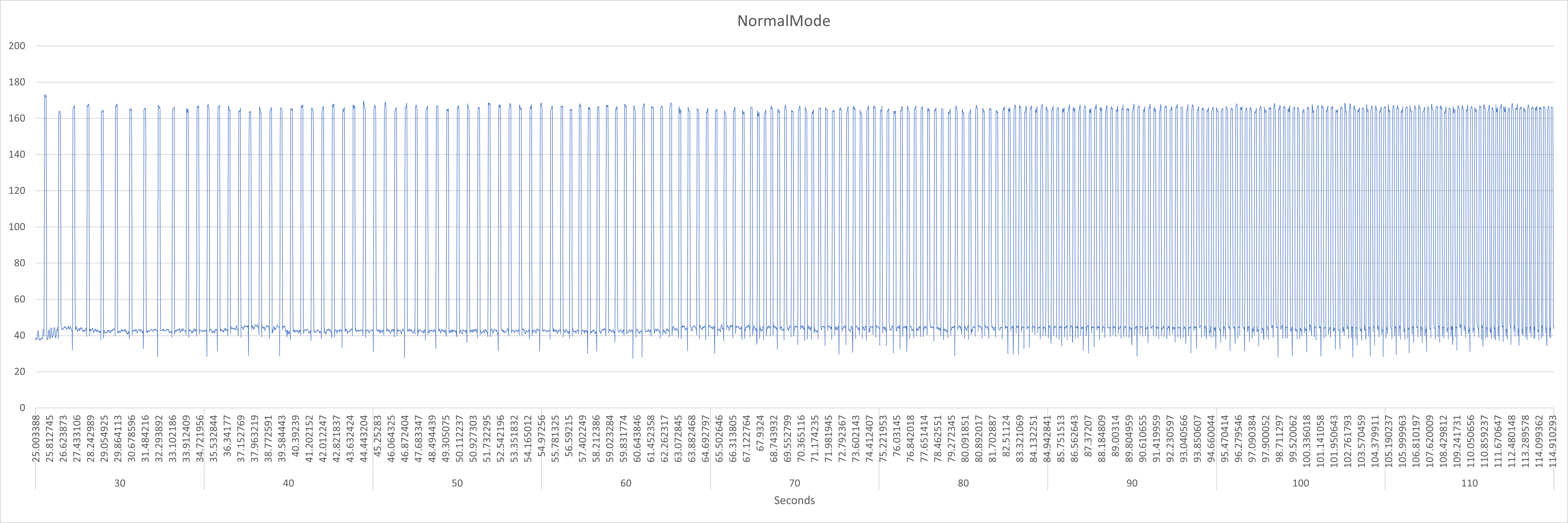
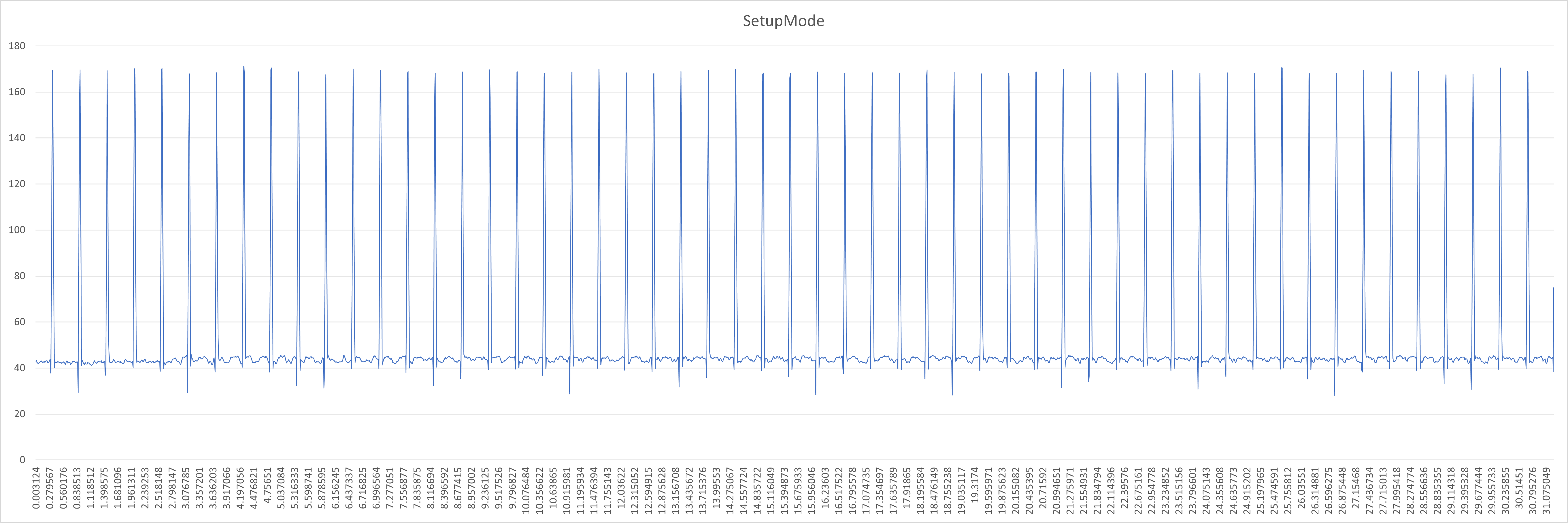
I ran the same setup through my test bench but couldn't reproduce the same as you found above.

First attachment shows the module running in Setup mode; constant pulsing to produce 15kph.
Second shows Normal mode. Since this is on the desk I had to trigger the reed sensor with a magnet on a drill.... However you can see as I slowly increase speed on the drill, the output behaviour still makes sense.

SetupMode.png NormalMode.png
 

Mervious

New Member
Jul 7, 2023
12
11
Finland
That's quite interesting I have to say. Maybe just triple check your reed sensor, try rotating it perhaps? If it were getting stuck closed occasionally it would produce this behaviour.

If not, It could be something to do with the magnet duration variable. I've got a setup on the bench at the moment actually so I'll see if I can reproduce the same.

I guess in practice though, to the motor it would just appear that you love skidding the back wheel sometimes!! That's not so bad! ;)

I tried to check the reed sensor now with a multimeter, but it seems to work as intended. At least I couldn't get it to get stuck with few times I rotated the wheel and let it rotate until stop.

Hi Mervious,

I ran the same setup through my test bench but couldn't reproduce the same as you found above.

First attachment shows the module running in Setup mode; constant pulsing to produce 15kph.
Second shows Normal mode. Since this is on the desk I had to trigger the reed sensor with a magnet on a drill.... However you can see as I slowly increase speed on the drill, the output behaviour still makes sense.

View attachment 120570 View attachment 120571

Yeah looks really good to me! Not sure where the errors / weirdness comes to my setup, but I think I can live with that 😄 Like you wrote, back wheel is just skidding sometimes at low speeds 😉 time to put the system back on. I just don't have time to take the bike for a spin for the rest of the week as I'm traveling, but I'll give it a try next week.
 

tatane

New Member
Jun 25, 2023
59
41
Southern France
Did some reading and then some testing simulating the potential behavior adding a simple R-2R circuit and a few code changes and ... must say I quite like the looks of it, might be time to test that with a real arduino and coil to see if it really works as intended and maybe tune a bit 😁

Screenshot 2023-07-21 022125.png
 

megabobra

Active member
Jul 24, 2022
221
246
Australia
Did some reading and then some testing simulating the potential behavior adding a simple R-2R circuit and a few code changes and ... must say I quite like the looks of it, might be time to test that with a real arduino and coil to see if it really works as intended and maybe tune a bit 😁

View attachment 120692

Hi Tatane, Is this to replicate the field you get from the positive/negative ends of the rim magnet as it passes?
 

megabobra

Active member
Jul 24, 2022
221
246
Australia
Hi Tatane, Is this to replicate the field you get from the positive/negative ends of the rim magnet as it passes?

I put together a H Bridge type circuit to reverse the current running through the coil, accounting for the positive to negative pole change of the magnet as it passes. Here's a quick demo of the coil output.

First attachment shows running in positive direction for one second, then off, then negative direction for one second, then off and repeat.

Second attachment shows this applied to the setup mode. Its interval and pulse width is for a 15kph constant speed. For half the pulse width the coil is positive, then for the second half the coil is negative, representing the passing magnet. The amplitude appears to be changing simply because phone sensor isn't fast enough to pick up the true readings at this rate.

Is this what you're thinking?

HBridgeDemo.png HBridge15Pulse.png
 

tatane

New Member
Jun 25, 2023
59
41
Southern France
I put together a H Bridge type circuit to reverse the current running through the coil, accounting for the positive to negative pole change of the magnet as it passes. Here's a quick demo of the coil output.

First attachment shows running in positive direction for one second, then off, then negative direction for one second, then off and repeat.

Second attachment shows this applied to the setup mode. Its interval and pulse width is for a 15kph constant speed. For half the pulse width the coil is positive, then for the second half the coil is negative, representing the passing magnet. The amplitude appears to be changing simply because phone sensor isn't fast enough to pick up the true readings at this rate.

Is this what you're thinking?

View attachment 120750 View attachment 120753
Exactly my thoughts 😀 idea being to replicate what the motor sees from the rim magnet ... the R-2R circuit has an "advantage" of being able to even create our curves to match the signature bosch may have at different speeds etc, but I'm yet to check if this translates to the coil as expected since R-2R won't get into negative offsets and just vary the output from 0-5V, making your solution likely better there ;)
 
Last edited:

EMTB Forums

Since 2018

The World's largest electric mountain bike community.

525K
Messages
25,954
Members
Join Our Community

Latest articles


Top