TQFreak's Dengfu E55 Build Thread

TQFreak

Active member
Dec 2, 2022
169
210
USA
I ordered an empty battery case on aliexpress, still waiting for the frame to be shipped but dengfu has delays...

View attachment 107401

I partially disassembled the battery supplied with the frame. Here is the process

1677132281406.png


1677132304101.png


1677132319480.png


1677132352182.png


1677132376917.png


1677132388070.png


1677132400731.png


1677132414269.png


1677132429355.png


The charge level indicator connected to BMS with 4 wires. I'm wondering if it is possible to replicate this functionality with different BMS for custom build battery?

1677132742856.png


1677132593567.png


1677132608935.png


1677132621922.png


1677132646414.png


1677132788581.png


1677132804122.png


1677132818600.png


1677132833754.png


1677132849692.png


1677132866734.png


1677132889548.png


They use something like white color silicone glue or maybe soft potting compound to secure the wires and the battery pack. The battery pack is protected with a few foam pads from contacting with the aluminum extrusion tube and glued with the same white rubbery stuff in the aluminum extrusion tube so I decided to not pull it out to keep it secured with the glue.
 
Last edited:

TQFreak

Active member
Dec 2, 2022
169
210
USA
You're right. If not then I can somehow have one fabricated for me.

Could you please also make one photo of the inside of the downtube. I want to understan if there the same 2 bolts that hold brackets securing all the housing.

Thanks!
Here is the part number for the plastic cover (Reention PLA0561). Maybe it will help you to find it.

1677133135897.png


Here are the close pictures from the inside of the frame downtube

1677133266498.png


Bottom of the downtube view from the motor area

1677133311645.png


Bottom of the downtube view from the battery area zoomed out

1677133412522.png


Bottom of the downtube view from the battery area zoomed in

1677133436653.png


Top of the downtube view from outside

1677133508480.png


Top of the downtube view from inside zoomed out

1677133559286.png


Top of the downtube view from inside zoomed in

1677133603175.png
 

TQFreak

Active member
Dec 2, 2022
169
210
USA
OK, I just printed the Kindernay shifter torque arm out of polycarbonate on an FDM 3D printer and it fits and works without issues. So if you are going to install Kindernay gear hub on Dengfu frame you can 3D print this part and fix the shifter housing with it. I would recommend you to use polycarbonate or PETG filament.

Here is the link to downaload the 3D file of the Kindernay shifter torque arm


You also are going to need a stainless steel M5x16mm screw


and a a stainless steel M5x10mm OD washer


1677134557338.png


1677134213358.png


1677134223591.png


Apply Loctite blue and install it

1677135073556.png


1677135089662.png


1677135108820.png


1677135150935.png
 

TeoElFeo

Member
Apr 13, 2022
179
58
Tallinn
Thank you for the detailed photos, they have been very informative!

Would it also be possible to measure the distance from the rear(motor) wall of the downtube until the ridge that is in the upper part of the tube. Basically trying to figure out how much flat space is there available for calculating custom batterypack size.
 

TQFreak

Active member
Dec 2, 2022
169
210
USA
Here is some information about the Innotrace X2 display for the Innotrace X1 controller can be helpful.

The Innotrace X2 display advanced settings are locked by a password. The advanced settings allow you to set the correct wheel diameter and pedal assist speed limit.

Innotrace still did not respond me about how I can reach those settings but I figured out it myself after sore research.

Here is Innotrace X1 (Eggrider) display manual, it has some similarities to Innotrace X2 display (Intelligent OLED Display DM03) and finctions


Here is the Innotrace X2 (Intelligent OLED Display DM03) display manual from the OEM manufacturer


To enter the display settings menu on Innotrace X2 display you have to turn the display ON and then press and hold the "M" button withing first 10 seconds after the display is turned ON.

Then you go to the "ADWSet"

1677208974885.png


Set the password 1657


1677209083444.png


And now you are in the Advanced Settings menu

1677209149537.png


Set your wheel diameter

1677209212146.png


Set your pedal assist speed limit

1677209291595.png


And here are all the advanced settings password combinations I found in the internet for Dengfu motor powered bike displays you can try in case the one I posted will not work for you so maybe you don't need to try 10000 combinations to find the one

1657
1919
1199
1801
0512
0486
0000
 

TQFreak

Active member
Dec 2, 2022
169
210
USA
Thank you for the detailed photos, they have been very informative!

Would it also be possible to measure the distance from the rear(motor) wall of the downtube until the ridge that is in the upper part of the tube. Basically trying to figure out how much flat space is there available for calculating custom batterypack size.
Here are the sizes. The distance between the ribs is 483mm. The opening length is 435mm. The distance between the bottom edge of the opening and the rib at the motor compartment is 24mm

1677211800653.png


Also pay attention the upper rib goes not straight vertical along the whole height, it makes turn, but that turning portion in opened up. The open portion of the rib which does not go straight vertical is about 71 mm. If you can squeeze the battery in this space you can probably ignore this rib turn

1677212645823.png
 
Last edited:

TeoElFeo

Member
Apr 13, 2022
179
58
Tallinn
Thank you for taking the time and giving those measures! Perhaps I didn't clearly explain which part I meant so I will try again.

I wanted to ask about the distance between the inner side of the motor rib and the very begining of the upper rib.

In fact I think the battery shape will follow the upper rib so I am trying to figure out how many rows of batteries I can fit before having to make the odd shape placement. Also what is the inner width of the downtube?
 
Last edited:

TQFreak

Active member
Dec 2, 2022
169
210
USA
Thank you for taking the time and giving those measures! Perhaps I didn't clearly explain which part I meant so I will try again.

I wanted to ask about the distance between the inner side of the motor rib and the very begining of the upper rib.

In fact I think the battery shape will follow the upper rib so I am trying to figure out how many rows of batteries I can fit before having to make the odd shape placement. Also what is the inner width of the downtube?
If you will be able to squeeze the battery somehow through the lower rib opening to the motor it will add 19mm. Here is the distance between the lower rib to the motor. So you will have 483mm+19mm=502mm between the motor and the upper rib.

1677299611260.png


The inner section of the downtube is 115mm x 84mm. There is also a couple of glued bottle mount inserts protrude 10 mm inside the internal space of the downtube

1677300008744.png


The odd shape upper rib is about 45mm wide if measured along the downtube length

1677300284352.png
 

TeoElFeo

Member
Apr 13, 2022
179
58
Tallinn
Thank you so much! Now I have all the measurements needed.
Also wanted to ask if the grey cylinder in between bottle cage mounts is a threaded mount for cable routing bracket?
 

TQFreak

Active member
Dec 2, 2022
169
210
USA
Thank you so much! Now I have all the measurements needed.
Also wanted to ask if the grey cylinder in between bottle cage mounts is a threaded mount for cable routing bracket?
There are two grey cylindrical threated mounts for the two aluminum brackets supplied with the frame for cables routing. They occupy about the same 10mm height with attached aluminum bracket as the brown bottle mounts threated cylinders.

1677344216369.png


1677344233567.png


1677344258483.png


1677344271873.png
 

TeoElFeo

Member
Apr 13, 2022
179
58
Tallinn
Perfect. I was planning to use them to attach straps to the frame that will hold my custom battery.

In theory I should be able to fit 48v 30ah battery. In practice I will find that out in a couple of months once I get the frame 🙂
 

TQFreak

Active member
Dec 2, 2022
169
210
USA
Kindernay VII shifter hoses are not long enough, so I purchased 10 meters of 2.0*5.0mm hydraulic hose


1677450022247.png

In order to have access to the swingarm cables holes I detached the lower mound of the swingarm.

1677450769056.png


The holes for the cables in the swingarm allow to route only one cable. Kindernay shifter requires two hoses. So I enlarged the right cable opening with Dremel

1677450524101.png


1677450588200.png


Then I enlarged the original hole

1677450840199.png


And drilled another hole for second hose near the first one starting from small drill bits and following ladger drill bits

1677450919971.png


So now I have two holes large enough to route two hoses through the swingarm

1677451001358.png


Cleaned the carbon dust with vacuum cleaner

1677451061198.png


1677451092125.png


Pushed 2 hoses through the swingarm and picked them from the swingarm opening

1677451151867.png


1677451174213.png


Cut both hoses with extra length from the main spool

1677451305636.png


1677451328525.png
 

TQFreak

Active member
Dec 2, 2022
169
210
USA
The nest thing I did is I routed the Magura MT5t brake hose through the left side of the swingarm.


Attached the brake lever to the handlebar so the hose goes up

1677451431986.png


Clipped the brake hose off at the brake lever

1677451530793.png


1677451545050.png


Plugged the hose with the plug supplied with the Magura brake kit

1677451587755.png


Clipped off the plug head so it will not interfere with the mall channel in the swingarm

1677451666174.png


1677451680643.png


Attached the cable frame grommet supplied with the frame to the hose

1677451737928.png


Routed the brake hose through the left side of the swingarm

1677451799412.png


1677451814355.png


Routed the Kindernay and the brake hoses through the brame and hanged the brake hose at the high point so it will not leak with oil

1677452003355.png


Clipped the hose grommet to the place

1677451866290.png


Attached the swingarm back

1677451905687.png


Attached the rear brake caliper

1677452064024.png


Then I cut about 200mm of flexible plastic tube (4mm inside diameter, 6mm outside diameter) and cut at along the length

1677452194179.png


And attached it to the brake hose where it goes between the swingarm and the frame to protect it from rubbing on the frame

1677452272481.png


1677452289616.png


1677452307888.png


Secured it with electrical tape

1677452343202.png


Attached the magnet sensor supplied with the Innotrace X1 motor

1677452394542.png


1677452414822.png


1677452430537.png


1677452444019.png


Routed it into the frame

1677452475777.png


Secured it with zipties

1677452499678.png


1677452529590.png


Installed the magnet sensor rubber cover supplied with the frame

1677473660498.png


Detached the rear brake from the handlebar keeping the tube faced up and placed the frame on side to proceed with cables routing

1677452636460.png


Attached the brake hose open end to the highest point so it will not leak

1677452729952.png


Routed the dropper post cable housing supplied with the dropper post PNW PUGET MTB LEVER Puget 2x Lever

1677452849863.png


1677453001445.png


1677453058560.png


1677453084213.png


Attached the bushing to the cable

1677453129088.png


1677453159972.png


Attached the cable housing cap to the cable housing on the dropper post end

1677453204091.png


Routed the cable though the housing

1677453233009.png


Routed the motor harness

1677453359824.png


Attached the fork and handlebar

1677453414462.png


Put the frame in upright position, attached the brake lever to the handlebar and marked the rear brake cable cut place making sure the brake cable has enough slack inside the frame to make turn in the frame steering head and around the battery upper mount

1677453534763.png


Removed the brake hose shroud from the brake lever and attached it on the hose

1677453634184.png


1677453644048.png


Detached the nut from the brake and attached it on the hose

1677453692597.png


1677453735478.png


Attached the olive supplied with the brake kit to the hose

1677453823643.png


Trimmed the hose

1677453856570.png


Attached the hose insert supplied with the brake

1677453882813.png


1677453899108.png


Detached the original hose end from the brake lever and discarded it

1677453783900.png


Attached the trimmed hose to the brake lever

1677453932861.png


1677453946712.png
 
Last edited:

TQFreak

Active member
Dec 2, 2022
169
210
USA
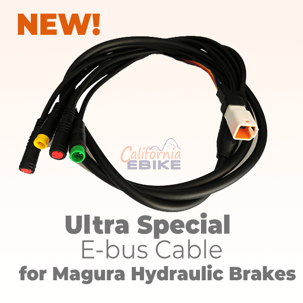
The Bafang m620 wiring harness supplied with Innotrace X1 motor has yellow 3 pins connectors for brakes e-stops but those connectors are incompatible with Magura MT5e brake connectors (2 pins).

You can make them compatible using this method


But I decided to purchase another Bafang m620 harness with Magura MT5e connectors


Unfortunately this cable is shorted than the original Bafang m620 harness and it is too short to fit Dengfu e55 17" frame

1677454746485.png


So I decided to use these two cable to make one long cable with Magura MT5e connectors

I cut a piece on the motor side from the original harness long enough


1677454689673.png


Removed part of the main insulation

1677454799553.png


1677454815459.png


Cut off the plug from the Bafang m620 MT5e cable

1677454854945.png


Trimmed the wires with matching colors to the stepped lengths (to prevent growing thickness of the cable and possible shortage)

1677454904633.png


1677454924418.png


Stripped and tinned the wires

1677455011469.png


1677455027804.png


Attached the harness sleeve to the motor plug exposed wires area to protect the exposed wires and to keep them flexible at the same time

1677455117524.png


Secured it with heat shrink tubes with adhesive liner

1677455151436.png


Attached the heat shrink tubes with adhesive liner to the cable and to the wires

1677455205817.png


Soldered the wires with corrsponding colors and leghts

1677455238488.png


Fused the heat shrink tubes

1677455271123.png


1677455291928.png
 

TQFreak

Active member
Dec 2, 2022
169
210
USA
To figure out where to trim the dropper post cable I attached the Kindernay Onesie shifter to the handlebar to the position where it supposed to be, attached the the dropper post with attached dropper post cable, attached the dropper post lever where it supposed to be, maintained proper slack of the dropper post cable inside the frame so it goes in the steering tube and round the battery upper mount without interference and marked the cable trim line

1677455874285.png


1677455905789.png


Removed the dropper post and the cable from the cable housing and trimmed the cable housing

1677456203251.png


Attached the cable to the cable housing

1677456245447.png


Connected the cable to the dropper post and attached the dropper post to the frame

1677456280757.png


Attached the lever housing cap to the lever side of the cable

1677456316312.png


Attached the cable guide

1677456347417.png


Attached the cable to the lever

1677456372990.png


1677456397290.png


1677456416892.png
 

eugene8

Member
Nov 12, 2022
27
4
mainland
A sheath for shifter has metal housing inside to prevent abrasion. The hydraulic one is made of plastic. Better find a dedicated shifter sheath for it to live a long happy life ))
 

BojanZ

New Member
Oct 10, 2022
46
21
Slovenia
Here is some information about the Innotrace X2 display for the Innotrace X1 controller can be helpful.

The Innotrace X2 display advanced settings are locked by a password. The advanced settings allow you to set the correct wheel diameter and pedal assist speed limit.

Innotrace still did not respond me about how I can reach those settings but I figured out it myself after sore research.

Here is Innotrace X1 (Eggrider) display manual, it has some similarities to Innotrace X2 display (Intelligent OLED Display DM03) and finctions


Here is the Innotrace X2 (Intelligent OLED Display DM03) display manual from the OEM manufacturer


To enter the display settings menu on Innotrace X2 display you have to turn the display ON and then press and hold the "M" button withing first 10 seconds after the display is turned ON.

Then you go to the "ADWSet"

1677208974885.png


Set the password 1657


1677209083444.png


And now you are in the Advanced Settings menu

1677209149537.png


Set your wheel diameter

1677209212146.png


Set your pedal assist speed limit

1677209291595.png


And here are all the advanced settings password combinations I found in the internet for Dengfu motor powered bike displays you can try in case the one I posted will not work for you so maybe you don't need to try 10000 combinations to find the one

1657
1919
1199
1801
0512
0486
0000
Man, I have to try these paswords, thanks! I also have the same stuff from innotrance as you, unfortunately their responses are very bad and still got no answer from them about this password, even though I emailed them at least three times how to change wheel diameter!! Btw, my stickers on the motor are the same as yours. Have it on E22 frame and set it to 40A max current.
 

rezystor1990

Member
Feb 1, 2023
28
48
Poland
If it's not a problem, you can measure the length:
- the length of the rear brake cable
- the length of the Kindernay cable
- the length of the line to the adjustable seatpost

My frame is still in China :( I currently have a M620 with a seroxat frame, I will be transferring all the equipment to the new frame. If I had the dimensions, I would check if my cables are long enough or do I need to buy new ones.
 

TQFreak

Active member
Dec 2, 2022
169
210
USA
I can not measure exact length of those cables - they are already installed on the frame. I can give you rough length when I will have time to measure it but I would not trust those numbers if you are planning to use it to trim your cables.
 
Last edited:

TQFreak

Active member
Dec 2, 2022
169
210
USA
If it's not a problem, you can measure the length:
- the length of the rear brake cable
- the length of the Kindernay cable
- the length of the line to the adjustable seatpost

My frame is still in China :( I currently have a M620 with a seroxat frame, I will be transferring all the equipment to the new frame. If I had the dimensions, I would check if my cables are long enough or do I need to buy new ones.
OK, I did rough measurements:

Rear brake hose length is about 2000mm

Kindernay each hose length is about 2000mm

Post dropper cable length is about 1670mm

Front brake hose length is about 1000mm

Again, do not trim the hoses and the cables to this lengths, this is rough data I measured without detaching the cables from the frame.
 

TQFreak

Active member
Dec 2, 2022
169
210
USA
For the wheels rims I purchased a couple of Nextie [Jungle Fox II] 29" MTB Rim 52mm with 32 holes


1678245313684.png


The front hub is SRAM 900 Front Hub - 15 x 110mm Boost, 32H, 6-Bolt, Black from eBay


1678245411479.png


The spokes are custom cut 2mm black SAPIM spokes from eBay

16 spokes 276mm long for front wheel brake side 3 cross pattern
16 spokes 279mm long front wheel non-brake side 3 cross pattern
32 spokes 253mm long for rear wheel Kindernay 32H SWAP Shell both sides 2 cross pattern


1678246240088.png


Nipples are DT Swiss Brass Nipple 2.0mm


1678246416625.png


Spokes threat locker is Wheelsmith Mini Spoke Prep, 15ml - Blue


1678246482266.png


Both tubes are MAXXIS Welterweight Tube 29x2.0-3.0 PV 48mm 0d


Both tires are WTB Ranger 3.0 x 29 TCS Light/Fast Rolling 60tpi Dual DNA SG2 tire


1678246611955.png


Rim tape is WHISKY - Tubeless Rim Tape - 45 mm Wide, 10 m Long


1678246760627.png


Reflectors are Labewin


1678246864518.png


Cleaned the spokes

1678246940390.png


Applied the threat locker

1678246974138.png


Lubed the nipples to rim contact surface

1678247009298.png


Laced the front wheel

1678247038987.jpeg


1678247059302.png


1678247122478.png


1678247183028.png


Trued the wheel on the fork with a piece of cardboard and a couple of zip ties


1678247242493.png


1678247270419.png


1678247287357.png


Set spokes tension around 100-120 kgf

1678247352312.png


Cleaned the rim internal surface with alcohol and applies two layers of the rim tape

1678247395709.png


1678247460102.png


Cut the hole for the inflation nipple

1678247495528.png


Attached the tire and the tube

1678247525439.png


1678247557217.png


Inflated to around 35 psi to seat the tire bead and dilated to 25 psi

1678247620764.png


1678247641336.png


Attached the brake disk

1678247703722.png


Attached the wheel reflector

1678247745045.png


Attached the spoke reflector

1678247789723.png


1678247837270.png
 

TQFreak

Active member
Dec 2, 2022
169
210
USA
And here is the front wheel

1678247911254.png


1678247931278.png


Then I laced the rear wheel

1678247976801.png


1678247991752.png


1678248010692.png


1678248035709.png


1678248048768.png


Trued it on the bike swingarm with a piece of cardboard and a couple of zip ties

1678248100052.png


1678248127992.png


Applied two layers of the rim tape

1678248160636.png


Attached the Kindernay VII gear hub to the wheel

1678248423198.png


1678248470545.png


Attached the brake rotor spacer and the brake rotor

1678248506797.png


1678248525563.png


1678248539570.png


Attached the torque arm with the spacer cup

1678248567296.png


Attached the cog

1678248597372.png


Attached the reflectors, attached the tire and the tube, seated the tire bead with pump and deflated the tire (It is not possible to attach this rear wheel to the Dengfu E55 with inflated tire, it needs more room to reach the rear hub slots in the swingarm).


1678248816565.png


Attached the deflated wheel to the swingarm

1678248872848.png


Inflated it

1678248899712.png


This rear wheel maintains about 1 mm gap with the mud cover rubber when it is inflated to 25 psi

1678248993213.png


Attached the speed sensor magnet

1678288155020.png


1678288172582.png


1678288206717.png
 
Last edited:

TeoElFeo

Member
Apr 13, 2022
179
58
Tallinn
I would say that 1mm gap is far from ideal... Things flex in the rear triangle a bit and mud and some debri can get stuck between the tire and frame. Also if the wheel good out of true it might start rubbing on the sides. Why such a peculiar choice of tyres? To me 29x2.6 seems plenty
 

TQFreak

Active member
Dec 2, 2022
169
210
USA
I want to fit the widest tires possible because of they look better and performs better on sand and snow.

Sneak pick. This 52V 3000W Innotrace motor combined with 46T chainring, 14T cog, Kindernay VII at highest gear (2.068 gear ratio) and 29" wheel is able to spin the wheel over 70mph (110kmh) with the throttle

1678289140548.png


1678289160601.png
 
Last edited:

TeoElFeo

Member
Apr 13, 2022
179
58
Tallinn
Looks nice! In reality I doubt that 3kw motor will allow you to get to that speed simply due to rolling and air resistance. Nonetheless it will be a very fast bike. Did the 46t chainring come stock with the Innotrace?

I have ordered my frame already and I am planning to go Innotrace with the motor.
 

TQFreak

Active member
Dec 2, 2022
169
210
USA
No, the Innotrace went with 44T steel chainring. By the way 44T chainring will interfere with the swingarm if mounted on the internal face of the spider. It looks like 42T chainring is the biggest chainring can be mounted on the internal face of the spider without interfering with the swingarm. The external face of the spider allows to mount 46T chainring maximum without touching the swingarm.

I purchased an aluminum 46T chainring with integrated guard and mounted it on the external face of the spider.
 

Bengy22

Member
Aug 25, 2022
97
58
USA
Bike is looking awesome! Those tires are huge, and the kindernay is looking sweet, loving the huge detailed write up you are going for the build. And looks like you are getting close to doing a test ride which sound be fun to hear about!
 

TeoElFeo

Member
Apr 13, 2022
179
58
Tallinn
No, the Innotrace went with 44T steel chainring. By the way 44T chainring will interfere with the swingarm if mounted on the internal face of the spider. It looks like 42T chainring is the biggest chainring can be mounted on the internal face of the spider without interfering with the swingarm. The external face of the spider allows to mount 46T chainring maximum without touching the swingarm.

I purchased an aluminum 46T chainring with integrated guard and mounted it on the external face of the spider.

Looking at the spider I would say the chainring is meant to be mounted on the external side. How does the chain line look when mounted externally?
 

Dado

Active member
Jun 28, 2022
576
406
Bratislava
Tqfreak, you are crazy!
Thanks for excelent photos. Your build must have taken hundreads of hours. Kudos to the stickers. And also to your craftmanship.

Anyway have also Inno and also very bad experience. That company is a joke.
Motor came also not setup as I ordered, X2 display does not work with their controller ( Rico did not want to refund). I had faulty torque sensor from factory! Where is some qc testing? And also faulty throttle. I had to buy programming cable (I think it is intention to ignore your setup then u need to buy programmer also)
I can share a setup, been experimenting a while.
 

EMTB Forums

Since 2018

The World's largest electric mountain bike community.

522K
Messages
25,758
Members
Join Our Community

Latest articles


Top