I've found this thread invaluable while making a range extender for my 2017 Jam2 so I thought I'd write up what I did in case anyone else finds this useful. First, some irrelevant background: my Jam 2 is running a -2 HA adjust headset, a 170mm fork and increased 153mm rear travel (using a 60mm stroke shock rather than 55mm). I run a 30mm wide rear rim and a 2.3 tyre , with a 2.8 front on the standard 40mm 27 in rim.
I liked the packaging of the orbea rise range extender. This is a 1.4kg 252Wh battery that fits in a waterbottle compatible mount so you can swap between bottle and battery in seconds:
RS RANGE EXTENDER RISE M
To get it to fit I first needed to attach the orbea water bottle mount. To do this I had to turn down the large focus jam rail screw heads on a lathe to get enough clearance (very bottom screw head in this picture):
Once that was done, I cut the orbea power cable (that comes in the kit) and attached one end to a Jam 2 spec rosenberger cable I ordered from mouser:
https://www.mouser.co.uk/ProductDetail/Rosenberger/C003-04-2000-C?qs=sGAEpiMZZMsvnOgGvSjZeLsLOOYFAZjZnmmFgZB4JFu6BZmNADaSRQ==
I had assumed the orbea battery would have a +36v, 0v somewhere, but it did not. I tried every possible combination of bus wire attachments while keeping the two power cables the same (literally all- I wrote out all combinations and went through them one by one- it took over an hour). None worked. So I opened up the battery.
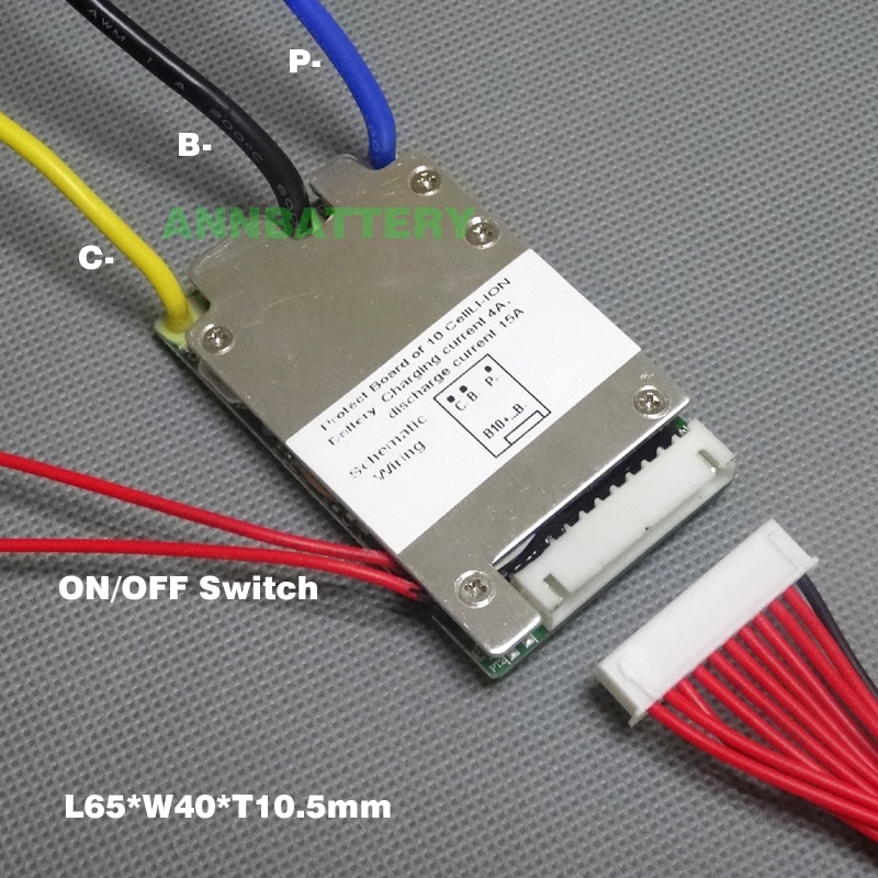
Inside I could see the pcb's controlling the battery. While it would have been great to keep this (it has an external on off switch and battery voltage led) I quickly abandoned hope of working out how to do it and simply bought the most compact bms I could find with an on off switch (space is very tight- I made a wooden mock up and it only just fitted).
36V lithium ion battery protection circuit 10S 36V/37V 15A BMS ON/OFF switch wires and small size L65*W40mm

gbr.grandado.com
Original bms:
When it arrived, I bought a soldering station, taught myself to solder, removed the old bms, and fitted the new. I soldered and used adhesive heat shrink on all joins.
new bms:

I didn't have a switch and I didn't want to put one on the case and lose the waterproof rating, so I soldered the switch wires together. I closed it all up and tested it and it worked fine- just like all the other range extenders in this thread (attach- instant power on and always reports battery state of the internal battery). Great, I thought, and went to bed happy. The next day after work, I connected it as before for a test and it did not work at all. I checked the outputs and both were at 0v. I opened the battery case up and cut the switch wires. On reattaching them it all reset and worked fine. For reliability, I realised I needed to be able to reset the switch. To get this, I wired the switch wires to two of the bus wires on the connector and then wired those together in the join in the external lead. Easy to say, hard to do when it means you have to cut your newly joined cable in half again..... However, I think this means that the bms will reset evey time I disconnect the cable and will only turn on once it is attached at the battery end. Which I hope will be quite a nice solution.
Finished? bms wiring:
Once this was all done, I connected everything back up and ...... nothing. The rosenberger connector had voltage but the bike would not turn on. Three terrible hours of undoing everything later (open case again cut open lead to check if bus wires were shorting), I realised the rosenberger connector was the problem. Another hour of testing (if I put swarf in the connector holes it worked, if I twisted it really hard, it worked) I realised the real problem. The voltmeter probes I used to check the voltage in the connector were precisely the correct size to bend the rosenberg connector springs back so they would not touch the male terminals on the bike. I cursed a lot. Then I bent them back gently with toothpick and a childs microscope and it all woked. Great. Now all I needed to do was to close the case up again (for the third time) and make the joining cable again (also for the third time). This was all plain sailing.
.jpeg")
Next up- charging. I had a £15 childs swegway charger (1 amp). Orbea wanted £100 for a charger. So I started with the swegway one. I also had the other half of the orbea cable I had cut off that I could wire to the charger. Sadly things were not simple. The orbea discharge cable had only the discharge cables wired and not the charge negative. So I had to open the connector up, dig out the termnals from some resin stuff then solder on a charge negative. Once done, it all worked fine.
I've tested it three or four times now and been very pleased. I've lost the use of the button and state of charge indicator, but it otherwise works very well. It's very convieniently packaged and completely rattle free. There is plenty of clearance to the (longer stroke and additional reservoir) shock.
When the reserve battery quits, I roll a ruber o ring onto the connector at the battery end then reattach. This is enough to disconnect the battery while still retaining it in place so I don't need to carry it.
Thank you to all the contributors to this thread- I would never have attempted this without seeing your solutions.


")