So this is where my confusion was early in the conversation . Why would I need an electromagnet if I already have either a current speed sensor ( factory fitted in frame ) or alternatively as you’ve said relocate my current in frame speed sensor with the reed switch taking its place at the wheel I’m assuming where the speed sensor was housed originally…..so my question as earlier posts ; why would I need an electromagnet as you guys had mounted in your motor area at all if my particular bike build isn’t looking to sense a rim magnet type of sensor ??
Surely for a system which simply has magnet on the rotor with speedsensor built in the frame there wouldn’t be a need for the electromagnet at all or am I missing something entirely in how your device actually works ?
Thx again
Tony
Surely for a system which simply has magnet on the rotor with speedsensor built in the frame there wouldn’t be a need for the electromagnet at all or am I missing something entirely in how your device actually works ?
Thx again
Tony
")


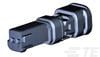
") Seems to be a 3D printed female version of the connector. It's from an german tuner. Can somebody told me if the aux plug is the same coding (dimensions) like the speed sensor plug. If so, i can try to reverse engineer the the female connector , and share the slt.
Seems to be a 3D printed female version of the connector. It's from an german tuner. Can somebody told me if the aux plug is the same coding (dimensions) like the speed sensor plug. If so, i can try to reverse engineer the the female connector , and share the slt.