The drawback of this solution is that Main Battery and Powermore can not be plugged at the same time because the motor will post an Error Code, so to install Powermore it would be required to remove the Main Battery and carry it in a backpack or in the Rear Rack, but as the weight is 4,4Kg and it'd be heavy to carry.
WARNING: I am sorry for the long and teachie post but I am parked at home for a few days and I have lots of time to spare.
So the perfect solution would be to carry both Main Battery and Powermore installed in the ebike and be able to select either of them by means of an external switch, and this is my Theoric Plan for that.
First let me tell you:
DON'T TRY TO DO THIS YET, for now this is just a theory, I am new to Bosch eBikes (One month and half) and I learned some of the following information by reading technical information and forums and this theory makes a lot of sense to me, but I might be wrong. So it would be good if somebody with more knowledge of Bosch cables and interfaces reviews it, and confirms if this is feasible or has any issue that I am not aware of, and if everything is correct, then may be somebody will be the first one to try and confirm the theory.
So let's start from the basics: the Battery internals:
- Main Battery (750W) has 60 x 18760 Lithium Cells and an electronic board (BMS) that:
- Controls and balance charge of the cells
- Monitors that battery internal parameters are within limits: Output Voltage, cell voltage, current and temperature
- Connects and disconnects battery output to motor or charger by using a solid state MOSFET Output switch.
- Has CAN Bus communication with Motor. CAN Bus is a Multipoint Bus developed by Bosch for the Car industry and is an Industry Standard, and now is also being used in Bosch powered ebikes.
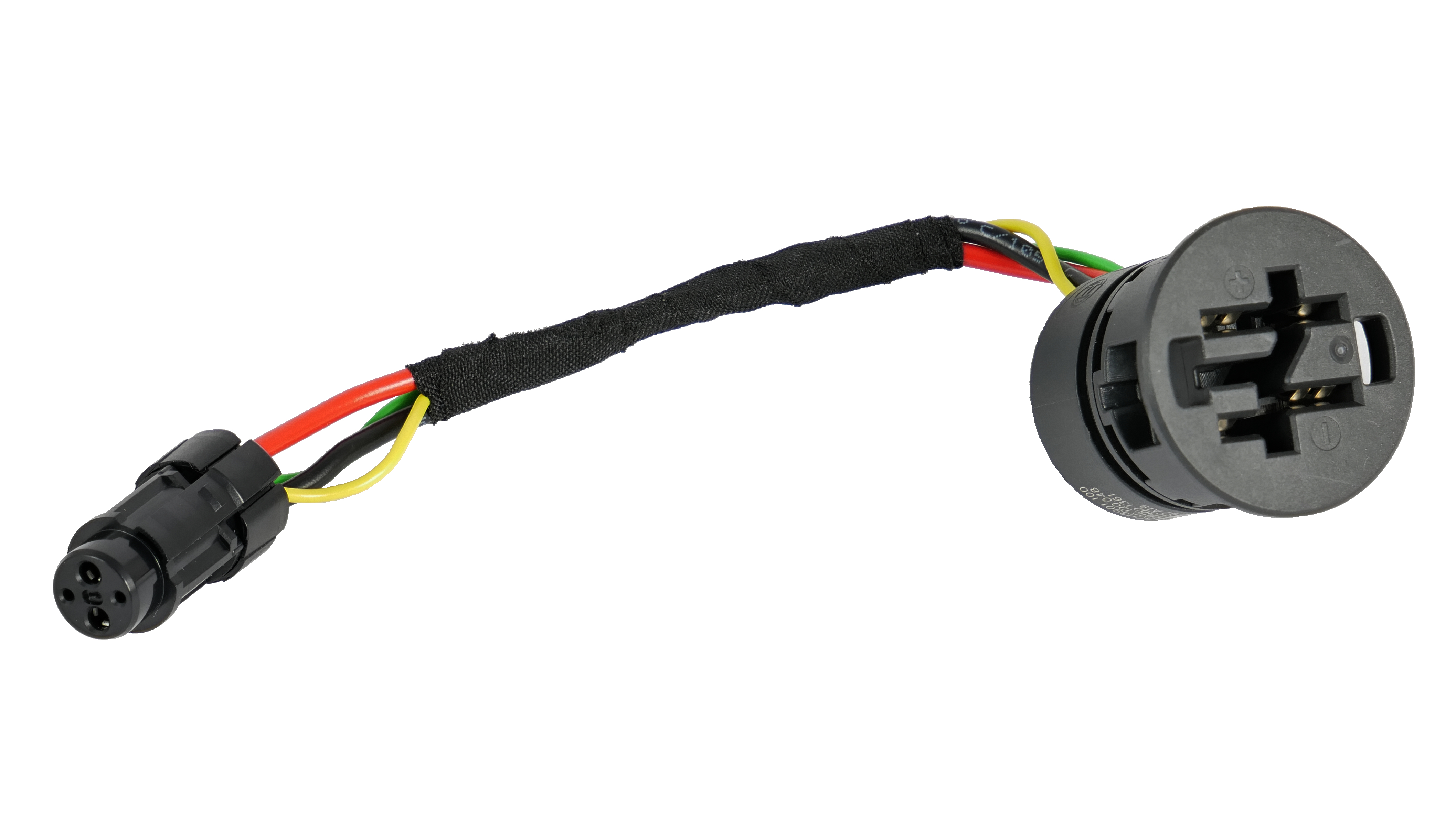
- Main Battery Connector to Motor has 4 wires:
- Two of them are the thick wires that carry the power to the motor: +36V (RED) and 0V(GND) (BLACK)
- The remaining two are thin wires (GREEN and YELLOW) for the CAN Bus.
The way the Motor and Battery connection works is:
- In case there is only one battery:
- When powering the bike ON, the battery MOSFET Output Switch is OFF, so the battery output voltage is not connected to the motor
- Then CAN BUS starts a handshaking data transmission between Battery and Motor to communicate that none of them has any error and all the internal parameters are within limits
- If everything is fine then the Battery switches ON its MOSFET Output Switch and now the Motor receives the voltage output from the battery and starts running.
- In case that there are two batteries in the system, like Main Battery and Powermore, and the motor configuration allows the two batteries (POWERMORE READY = YES).
- The Motor will communicate through the CAN Bus to both of them and it will select batteries sequentially by switching ON/OFF the batteries MOSFET Output switches:
- Motor will set Main Battery ON and Secondary Battery OFF, and after using 5% of the battery
- Then Motor will switch Main Battery OFF and Secondary Battery ON and continue the discharge.
- The previous cycle will be repeated until batteries are exhausted.
- That is, the 36V Output Voltage from both batteries will not be connected in parallel at the same time to the Motor because Motor is controlling MOSFET OUTPUT Switches of both batteries.
So the Theorical solution to have Main Battery and Powermore installed in the ebike would be to use a
Switch DPDT (Double Pole Double Throw) for Battery Selection and connect it the following way:
- Cut CAN wires from battery to motor
- Cut Can Wires from Charge plug to Motor
- Use a Multipole switch and connect:
- CAN wires from Battery to Input 1 of Multipole Switch
- CAN wires from Charge Plug to Input 2 of Multipole Switch
- CAN wires from Motor to Output of Multipole Switch
So now we can have Main Battery installed and Powermore plugged, but with the Switch we can select which Battery CAN BUS is connected to the Motor, and:
- This selected battery will perform the handshaking and switch ON its internal MOSFET Output Switch and power the Motor.
- The second, unselected, battery do not have the CAN Bus connected, so it will be invisible to the Motor and its internal MOSFEET Output switch would be OFF until selected by the switch.
The switch and cable:
- The ideal switch would be installed in the handlebar, there are many switches for motorbike use and may be one of them is type DPDT and could be used for this application.
- The cable to extend CAN Bus wires from motor and batteries to the switch could be one from a quality USB-C cable that has 6 internal wires.
The issues:
- This has not been tested, but soon after Powermore is released, there will be many people with expired bike warrany and eager to install Powermore doing experimentsto to install it, and then we will have more information about the feasibility of the installation.
- It will not be possible to charge the battery through the charge port because CAN Bus from Charger Port would be disconnected from Main Battery. The fix to this will need more thinking, the first idea would be to use a more complex switch with three positions:
- Position 1: CAN Bus from Motor connected to Battery
- Position 2: CAN Bus from Motor connected to Charge Port
- Position 3: CAN Bus from Motor connected to Charge Port AND Battery
And as I said before,
DON'T TRY THIS, wait untill this theory has been confirmed and somebody knowledgeable expert verifies it.


 www.youtube.com


 not sure I need 1000wh of battery though