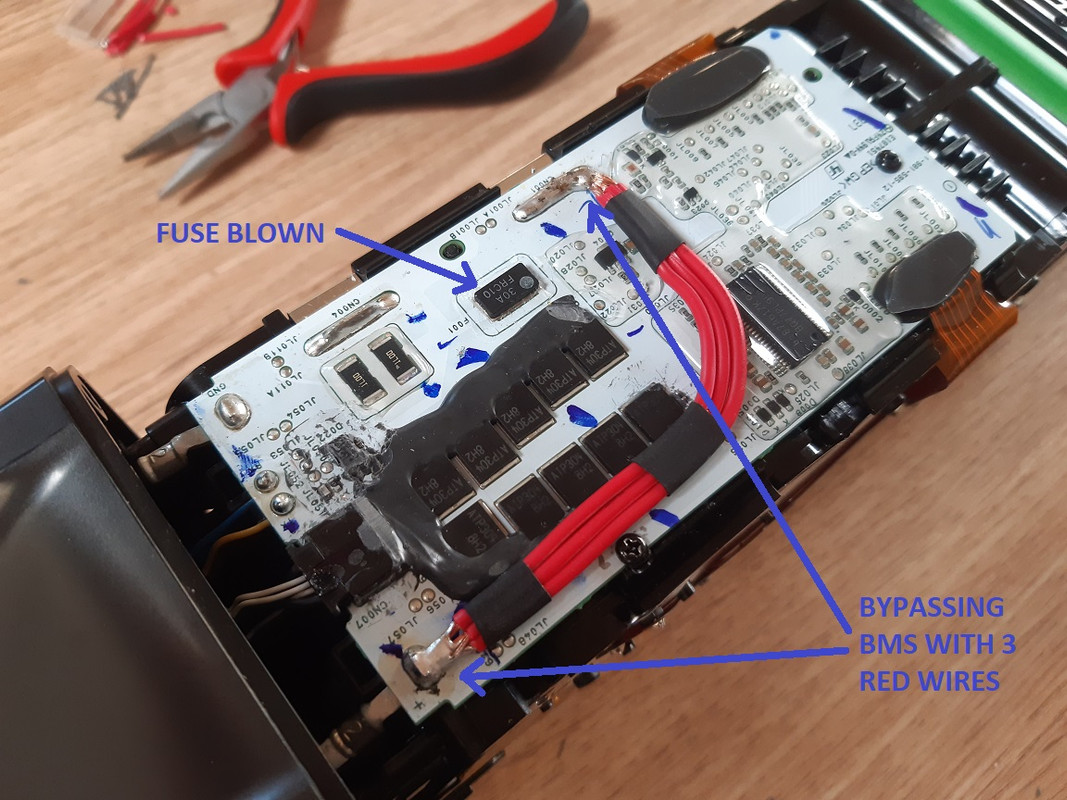
While waiting for the generic charger to arrive, i thought it would be fun to see why my charger is not letting me charge the "dead" battery.
So i hooked up a scope to the signals and powerline that runs from the charger to the battery BMS.
There is negotiation happening between the charger and BMS, so the charger knows the state of the battery and bms, and knows if it can safely apply charging power.
From what i was able to work out, there are 3 communication lines, 2 are simple UART RX and TX lines, the other doesnt do much (perhaps just a presence signal or something). Communication is running at 9600baud so its easy to capture and see what is going on.
Charger seems to be the master, the BMS responds to its commands. General packet structure (im using the first encountered packet as an example):
0x00 -> Start of packet
0x41 -> Command (can be anything, but below 0x80 i would think)
0x00 -> Length of payload that follows after this byte, in this case 0 bytes (there is no payload in this example)
0xF9 -> CRC-16/X-25 low byte calculation of the packet, starting from Command, ending with the payload
0x50 -> CRC-16/X-25 high byte calculation of the packet, starting from Command, ending with the payload
The BMS always responses to a command with a similar packet structure. However the Command byte now becomes the Response byte, which is equal to Command+0x80.
So the BMS responses to the previous example as follows:
0x00 -> Start of packet
0xC1 -> Response (equal to Command+0x80)
0x00 -> Length of payload that follows after this byte, in this case 0 bytes (there is no payload in this example)
0x35 -> CRC-16/X-25 low byte calculation of the packet, starting from Command, ending with the payload
0xDC -> CRC-16/X-25 high byte calculation of the packet, starting from Command, ending with the payload
I expect this first encountered packet to be something like a communication check, or presence check. Just to see if communication is good to go. There is no data payload, so no data is being exchanged yet.
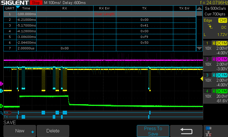
So with my good battery this whole setup looks something like this on my scope:
You can see the communication lines in yellow(RX), blue (TX), purple (presence line or something?) and Green (power line)
Since this battery is good and full the power line is only applied a short period, but communication consists of multiple steps and keeps going even after power is removed.
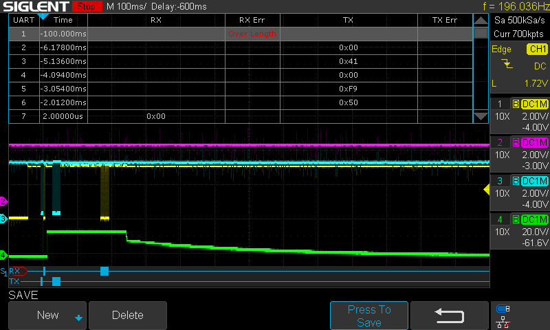
Now the "dead" battery:
So as you can see, that other than the initial command and response packet, there is only one other command and response packet (this one does have more data, i will show later). Even though power is applied for a short time (green line), it is immediately removed after the first payload packet and then communication halts completely. The charger will then start blinking its led (indicating an error).
So is there a clue to be found in that first payload packet?
Trying to decode the payload of the packets is difficult. I can only compare the good vs the dead battery. I have made several captures of the RX and TX data of both the good and dead battery at startup. There is a highly variable payload content but there are some consistencies. On that first payload response packet, the good BMS will always start its payload with the values: 0x30, 0x00. However the dead BMS will always start its payload response with 0x30, 0x25.
I will try to post a couple of CSV files with all the captured RX and TX data later. However, i suspect that 2nd payload byte flipping from 0x00 to 0x25 might be the indication of the BMS that it is bricked and prevents the charger from starting its charging process...


")